
Electricity Short Notes Class 10 Chapter 11 is your go-to for Quick Memorisation and Quick Revision.
And to learn the chapter, you must read your NCERT textbook, Chapter 11, Electricity.
Here inside“Electricity Short Notes Class 10 Chapter 11″ you will get:
- Short Snackable notes.
- Images make you understand the concepts well.
- Interactive animated visuals to play around with.
ELECTRIC CURRENT AND CIRCUIT
What is Electric Current?
- Charge flowing through a conductor = electric current
- Example: cells → bulb → glow (in torch)
Switch and Circuit
- Switch: creates a conducting link between the cell and the bulb
- Electric circuit: continuous, closed path for current
- Circuit broken → current stops → bulb off
Current Direction
- Current = rate of charge flow
- Metallic wires: electrons carry charge
- Convention: current = flow of positive charges
- Conventional direction = opposite to electron flow
Formula ,
I = Q / t
I = current | Q = charge | t = time
Units Table
| Quantity | Unit | Value |
|---|---|---|
| Charge | coulomb (C) | 1 C ≈ 6 × 10¹⁸ electrons |
| Electron charge | – | 1.6 × 10⁻¹⁹ C |
| Current | ampere (A) | 1 A = 1 C/s |
| Small current | milliampere (mA) | 1 mA = 10⁻³ A |
| Smaller current | microampere (μA) | 1 μA = 10⁻⁶ A |
Measuring Current
- Ammeter: measures current
- Connection: always in series
- Circuit flow: cell (+) → bulb → ammeter → cell (–)
ELECTRIC POTENTIAL AND POTENTIAL DIFFERENCE
Why Do Charges Flow?
- Charges need an electric pressure difference to flow
- In wires: potential difference drives electron motion
Role of Battery/Cell
- A battery produces a
potential difference across its terminals - Chemical action in the cell → creates a potential difference
- When connected to a circuit → charges move → current flows
- The cell expends stored chemical energy to maintain current
Potential Difference Definition
V = W/ Q
V = potential difference or voltage | W = work done | Q = charge
- V = potential difference | W = work done | Q = charge
- Meaning: work done to move a unit charge between two points
Unit: Volt (V)
| Term | Definition |
|---|---|
| Volt (V) | SI unit of potential difference; named after Alessandro Volta (1745–1827) |
| 1 volt | 1 joule of work moves 1 coulomb of charge |
| Formula | 1 V = 1 J C ⁻¹ |
Measuring Potential Difference
- Voltmeter: measures potential difference
- Connection: always in parallel across the two points
OHM’S LAW
👉 “Voltage pushes, current flows… but how much? Ohm’s Law tells us.”
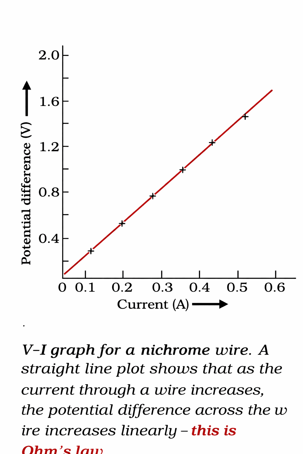
V–I Graph Observation
- V/I ratio ≈ constant in each case
- V–I graph: straight line through the origin
- Conclusion: V/I = constant ratio
Ohm’s Law Statement
- Law: Potential difference (V) across a metallic wire is directly proportional to current (I )
- Condition: temperature remains constant
Ohm’s Law Formula
V ∝ I → V/I = R → V = IR
V = voltage or potential difference
I = current
R = resistance
R = resistance = constant for given wire at given temperature
R = V / I
Resistance: Definition and Unit
- Resistance: the property of a conductor to resist the flow of charges
- SI unit: ohm (Ω), Greek letter Omega
| Condition | Definition |
|---|---|
| 1 ohm (Ω) | 1 volt / 1 ampere |
| Formula | R = V/I |
Current and Resistance Relationship
I = V/R
- Current ∝ 1/Resistance (inversely proportional)
- If resistance doubled → current is halved
Variable Resistance
- Purpose: increase/decrease current without changing the voltage source
- Variable resistance: a component used to regulate current
- Rheostat: a device used to change resistance in a circuit
Conductors vs Resistors vs Insulators
| Component | Resistance Level | Description |
|---|---|---|
| Good conductor | Low | Offers easy path for current |
| Resistor | Appreciable | Conductor with some resistance |
| Poor conductor | Higher | Resists current flow more |
| Insulator | Very high | Offers an easy path for current |
Why Resistance Exists
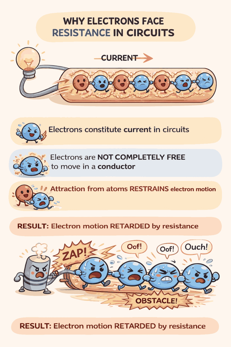
Resistance (Atoms 😈)
FACTORS ON WHICH THE RESISTANCE OF A CONDUCTOR DEPENDS
Resistance Depends On
1. Length (l) of conductor
R ∝ l
2. Area of cross-section (A )
R ∝ 1/A
3. Nature of material
Combined:
R = ρ l / A
- R = resistance | l = length | A = cross-sectional area
- ρ (rho) = electrical resistivity (constant for material)
Resistivity (ρ)
| Property | Details |
|---|---|
| Definition | Constant of proportionality in R = ρ l/A |
| SI unit | ohm metre (Ω m) |
| Nature | Characteristic property of material |
Resistivity Ranges
| Material Type | Resistivity Range | Conductivity |
|---|---|---|
| Metals/Alloys | 10⁻⁸ to 10⁻⁶ Ω m | Good conductors |
| Insulators (rubber, glass) | 10¹² to 10¹⁷ Ω m | Poor conductors |
Temperature Effect
Both resistance and resistivity vary with temperature
Practical Applications
- Alloys: higher resistivity than constituent metals; do not oxidise readily at high temperatures → used in heating devices (electric irons, toasters)
- Tungsten: used for electric bulb filaments
- Copper/Aluminium: used for electrical transmission lines
RESISTANCE OF A SYSTEM OF RESISTORS
Series Connection
Same current
different voltage
Parallel connection
Same voltage
different current
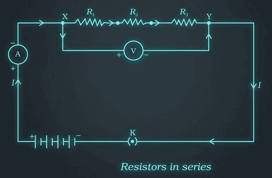
Resistors in Series
Current in
Series Circuit
- Current is the same at every point in a series circuit
- Ammeter reading unchanged regardless of position
- The same current I flows through each resistor
Potential Difference in Series
V = V₁ + V₂ + V₃
- Total potential difference = sum of individual potential differences
- V₁, V₂, V₃ = potential differences across R₁, R₂, R₃
Equivalent Resistance Derivation
| Steps | Application | Result |
|---|---|---|
| 1 | Ohm’s law (entire circuit) | V = I R |
| 2 | Ohm’s law (each resistor) | V₁ = I R₁, V₂ = I R₂, V₃ = I R₃ |
| 3 | Substitute in Eq. | I R = I R₁ + I R₂ + I R₃ |
| 4 | Cancel I | Rₛ = R₁ + R₂ + R₃ |
Key Conclusion
- Equivalent resistance (Rₛ) = sum of individual resistances
- Rₛ is greater than any individual resistance in series
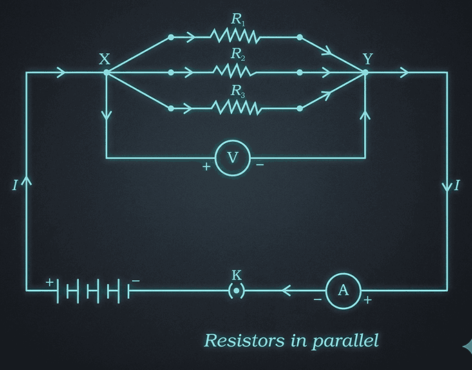
Resistors in Parallel
Current in a Parallel Circuit
I = I₁ + I₂ + I₃
- Total current = sum of currents through each branch
- I₁, I₂, I₃ = separate currents through R₁, R₂, R₃
Equivalent Resistance Derivation
| Steps | Application | Result |
|---|---|---|
| 1 | Ohm’s law (parallel combination) | I = V/Rₚ |
| 2 | Ohm’s law (each resistor) | I₁ = V/R₁, I₂ = V/R₂, I₃ = V/R₃ |
| 3 | Substitute in Eq. | V/Rₚ = V/R₁ + V/R₂ + V/R₃ |
| 4 | Cancel V | 1/Rₚ = 1/R₁ + 1/R₂ + 1/R₃ |
Key Conclusion
- Reciprocal of equivalent resistance (1/Rₚ) = sum of reciprocals of individual resistances
- Rₚ = equivalent resistance of parallel combination
Series vs Parallel Summary
| Feature | Series | Parallel |
|---|---|---|
| Current | Same through all resistors | Divides among branches |
| Potential difference | Divides across resistors | Same across all resistors |
| Equivalent resistance | Rₛ = R₁ + R₂ + R₃ | Divisions among branches |
Series vs Parallel: Practical Use
Series Disadvantages
- Same current everywhere → unsuitable for devices needing different currents (e.g., bulb + heater)
- One component fails → entire circuit stops
- Example: Fairy lights → one fused bulb → all off → hard to locate fault
Parallel Advantages
- Current divides → each device gets the required current
- Total resistance decreases → 1/Rₚ = 1/R₁ + 1/R₂ + 1/R₃
- One device fails → others keep working
- Ideal for gadgets with different resistances
Quick Compare
| Series | Parallel |
|---|---|
| Same current | Current divides |
| One fail → all off | One fail → others on |
| Higher total R | Lower total R |
| Not for mixed loads | Suitable for mixed loads |
HEATING EFFECT OF ELECTRIC CURRENT
Energy Source
- Battery/cell → chemical energy → potential difference → current flow
- The source expends energy to maintain the current
- Energy split: useful work (e.g., fan blades) + heat (temperature rise)
Heating Effect Definition
- Purely resistive circuit (resistors only) → all source energy → heat
- This = heating effect of electric current
- Applications: electric heater, electric iron
Heat Production Formula
H = V I t
H = heat | V = potential difference | I = current | t = time
Joule’s Law of Heating
Joule’s Law of Heating
H = I² R t
H = heat | I = current | t = time
| Factor | Relationship |
|---|---|
| Current (I) | H ∝ I² (for fixed R, t) |
| Resistance (R) | H ∝ R (for fixed I, t) |
| Time (t) | H ∝ t (for fixed I, R) |
Practical Use
- When voltage (V) known: first find I = V/R, then use H = I² R t
Practical Applications of the Heating Effect of Electric Current
Desirable vs Undesirable Heating
- Undesirable: Wastes electrical energy → heat; alters component properties
- Desirable: Used in heating/lighting devices
Heating Devices
(Joule’s Heating)
- Electric iron, toaster, oven, kettle, heater
- All convert electrical energy → heat via resistor
Electric Bulb
| Feature | Detail |
|---|---|
| Filament material | Tungsten (melting point 3380°C) |
| Why tungsten | High melting point; retains heat → emits light |
| Bulb filling | Chemically inactive nitrogen/argon → prolongs filament life |
| Energy split | Most → heat; small part → light |
Fuse: Safety Device
- Purpose: Protects circuit/appliances from high current
- Connection: In series with the device
- Working:
- Current > rated value → fuse wire heats → melts → circuit breaks
- Material: Metal/alloy with low melting point (Al, Cu, Fe, Pb)
- Construction: Wire encased in a porcelain cartridge with metal ends
- Ratings: 1 A, 2 A, 3 A, 5 A, 10 A, etc.
Fuse
Selection Example
- Device: Electric iron, 1 kW, 220 V
- Current: I = P/V = 1000/220 ≈ 4.54 A
- Fuse to use: 5 A (next higher standard rating)
ELECTRIC POWER
Definition
- Power = rate of doing work = rate of energy consumption
- Electric power = rate at which electrical energy is dissipated/consumed in circuit
Power Formulas
P = V I
P = I² R
P = V² / R
P = power | V = potential difference | I = current | R = resistance
Unit: Watt (W)
| Term | Definition |
|---|---|
| Watt (W) | SI unit of electric power |
| 1 W | 1 V × 1 A = 1 V A (Equation 11.23) |
| Larger unit | Kilowatt (kW) = 1000 W |
Electric Energy
- Formula: Energy = Power × Time
- Unit: watt hour (W h)
- 1 W h = energy used by 1 W device in 1 hour
- Commercial unit: kilowatt hour (kW h) = 1 unit
kW h to Joule Conversion
1 kW h = 3.6 × 10⁶ J
| Step | Calculation |
|---|---|
| 1 kW h | = 1000 W × 3600 s |
| = 3.6 × 10⁶ watt second | |
| = 3.6 × 10⁶ joule (J) |
![MCQs Light Reflection And Refraction Class 10 [Quiz Format], Important Questions!](https://studyless.in/wp-content/uploads/2026/01/Short-2_11zon.jpg)