
“Light Reflection and Refraction Short Notes” is no replacement of your NCERT textbook. These short notes are for revision and quick memorisation only.
First read the chapter from NCERT textbook and then come here for quick revision. Only the important concepts, definitions and points are populated here, therefore if you find something new here, go back to your NCERT textbook and read again and agian.
You can click on the links on the table of contents below to go to the relevant sections.
REFLECTION OF LIGHT
Laws Of Reflection
(i) Angle of incidence = Angle of reflection.
(ii) Incident ray, normal at the point of incidence, and reflected ray all lie in the same plane.
→ These apply to all reflecting surfaces, including spherical mirrors.
Plane Mirror Image Properties
- Always virtual and erect.
- Same size as the object.
- Image distance behind the mirror = Object distance in front.
- Laterally inverted
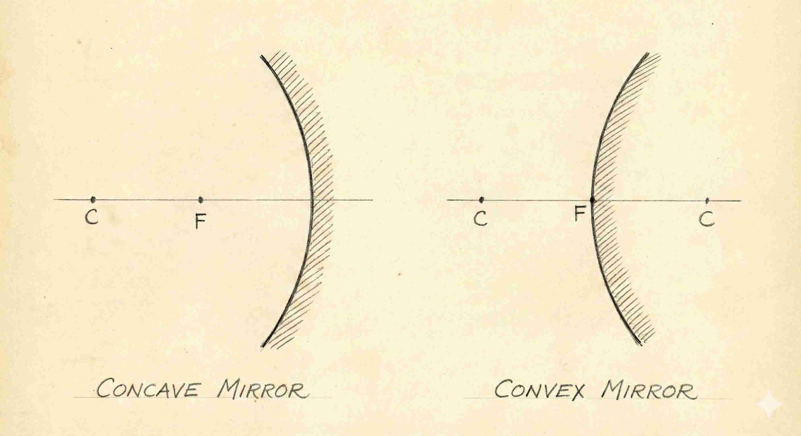
Spherical Mirrors
A reflecting surface is part of a sphere.
- Concave mirror: Reflecting surface curved inwards (toward the centre of the sphere).
- Convex mirror: Reflecting surface curved outwards.
Key Terms
| Term | Definition |
|---|---|
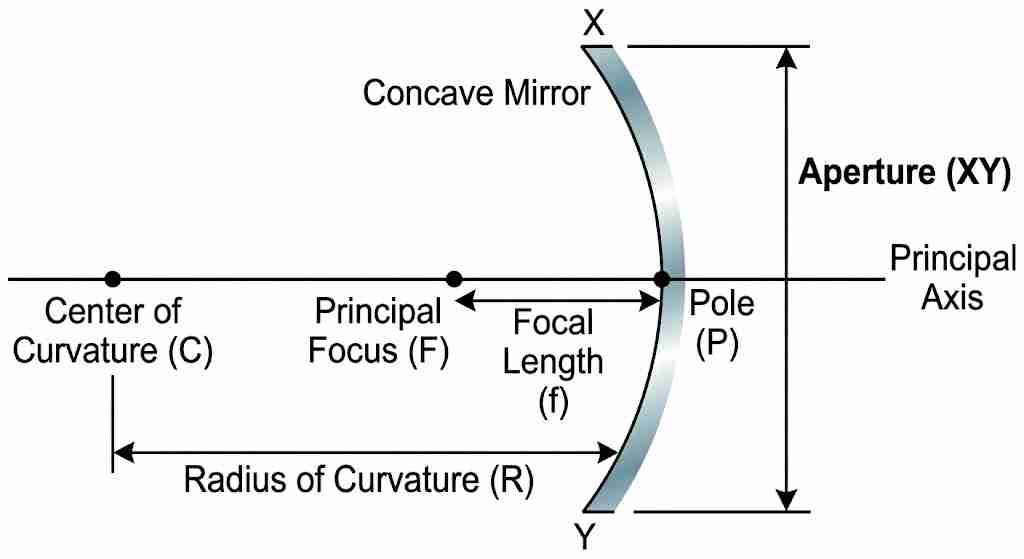
| Pole (P) | Centre of the reflecting surface (lies on the mirror). |
| Centre of Curvature (C) | Centre of the sphere of which the mirror is a part. • For concave mirror: C is in front. • For convex mirror: C is behind. |
| Radius of Curvature (R) | Distance between P and C. |
| Principal Axis | Straight line through P and C; normal to mirror at P. |
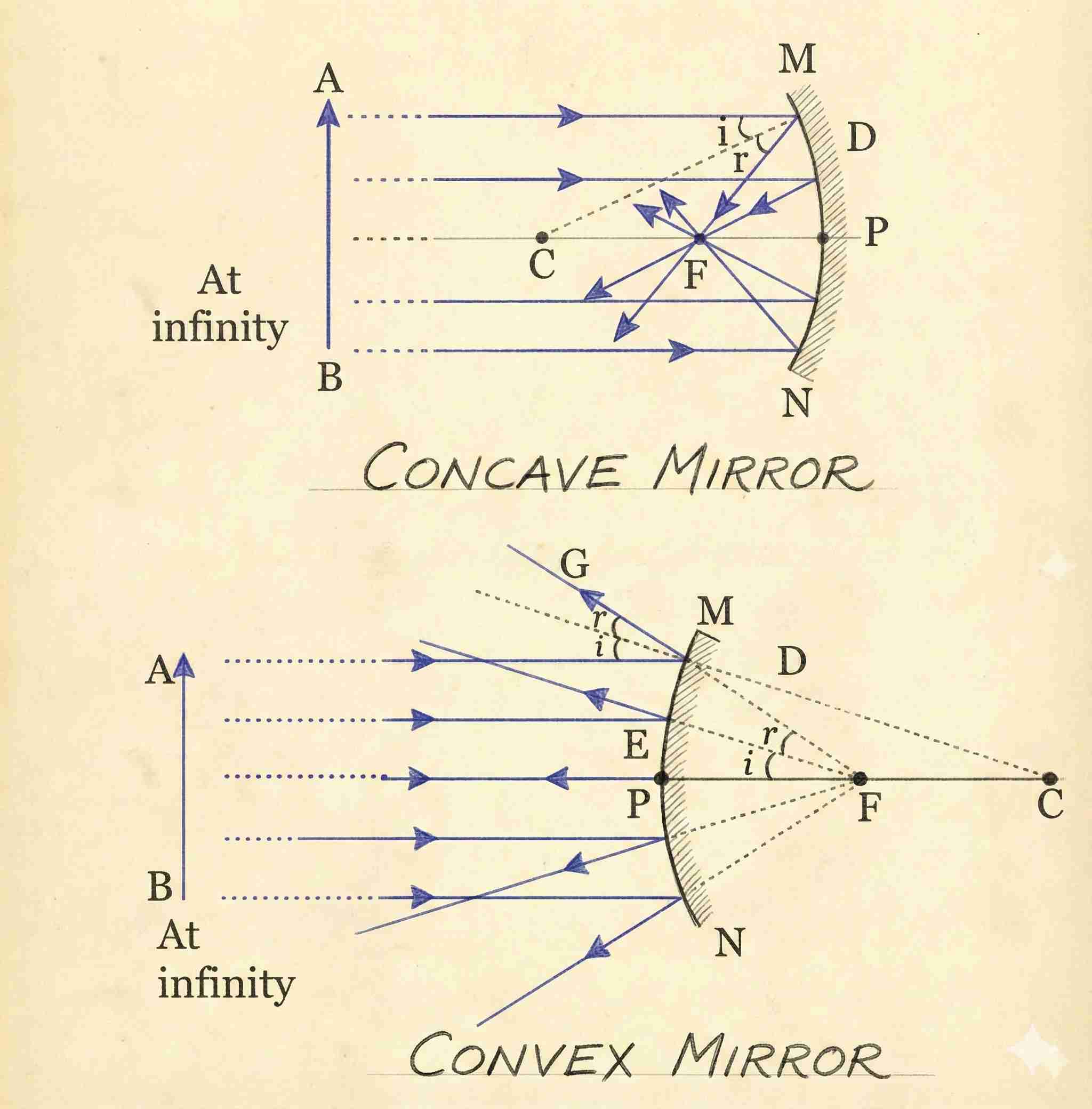
| Principal Focus (F) | Concave: Point where parallel rays converge after reflection. Convex: Point from which reflected rays appear to diverge. |
| Focal Length (f) | Distance between P and F. |
| Aperture | Concave: A point where parallel rays converge after reflection. Convex: Point from which reflected rays appear to diverge. |
Relation Between R and f
For spherical mirrors of small aperture
R = 2f
→ Therefore, F lies midway between P and C.
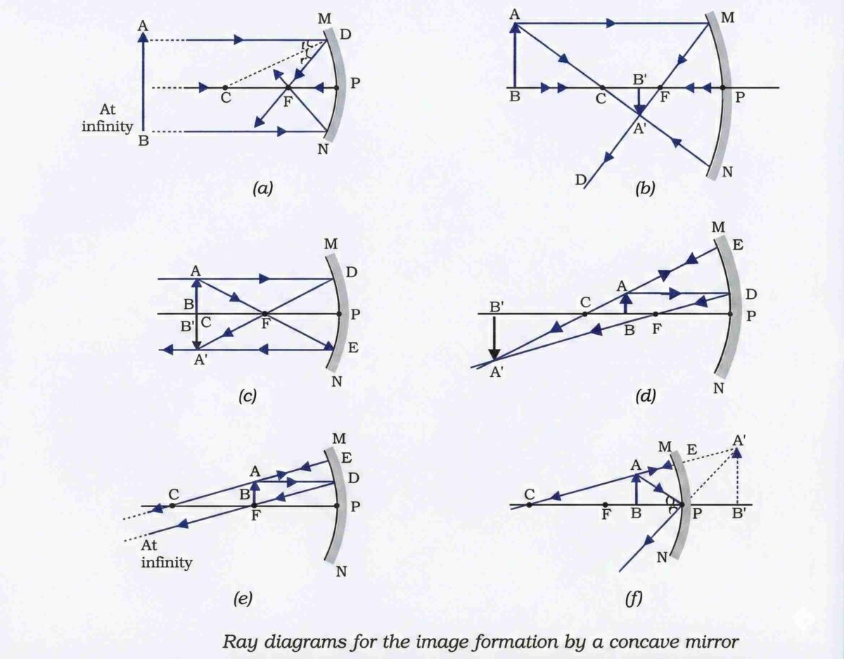
Image Formation by Spherical Mirrors
Concave Mirror – Image Characteristics
| Object Position | Image Position | Size | Nature |
|---|---|---|---|
| At infinity | At focus (F) | Highly diminished, point-sized | Real, inverted |
| Beyond C | Between F and C | Diminished | Real, inverted |
| At C | At C | Same size | Real, inverted |
| Between C and F | Beyond C | Enlarged | Real, inverted |
| At F | At infinity | Highly enlarged | Real, inverted |
| Between P and F | Behind the mirror | Enlarged | Virtual, erect |
Note: Only when the object is between P and F is the image virtual and erect; all other positions yield real and inverted images.
Ray Diagram Rules For Spherical Mirrors
Ray parallel to principal axis →
- Concave: Passes through F after reflection.
- Convex: Appears to diverge from F behind the mirror.
Ray through Focus (or directed toward F in convex) →
- After reflection, emerges parallel to the principal axis.
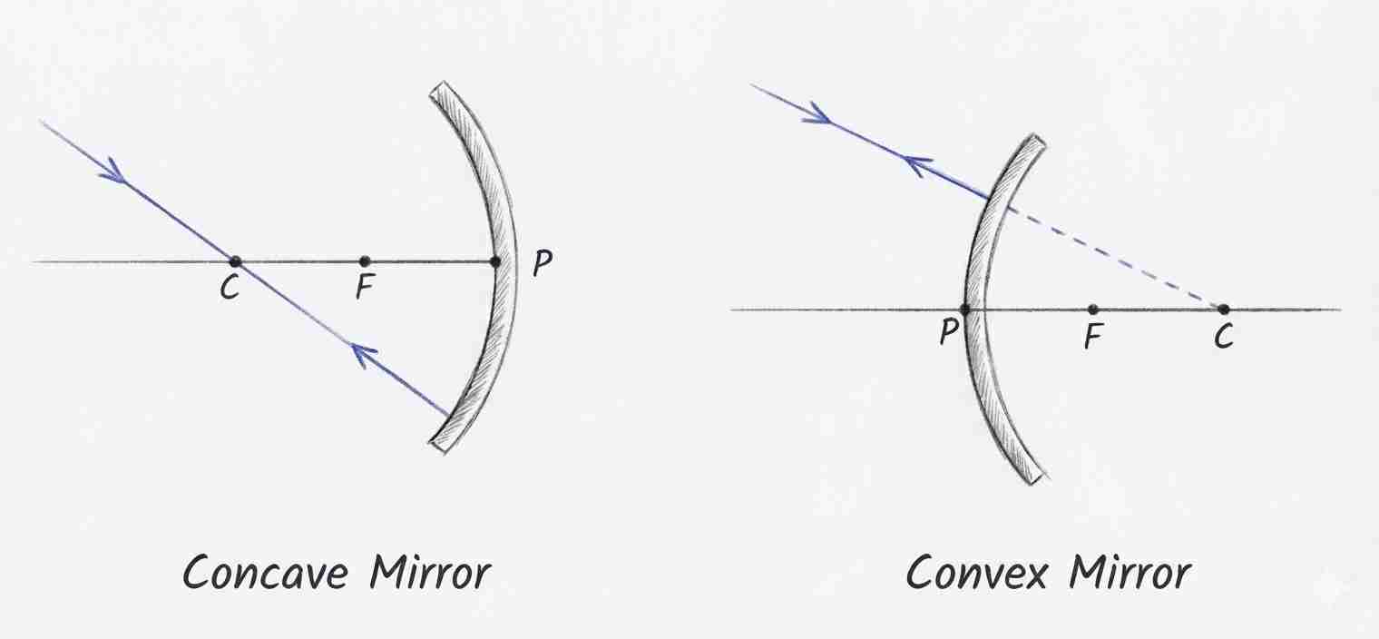
Ray through the centre of curvature (or directed toward C in convex) →
- Reflects along the same path (incident along normal).
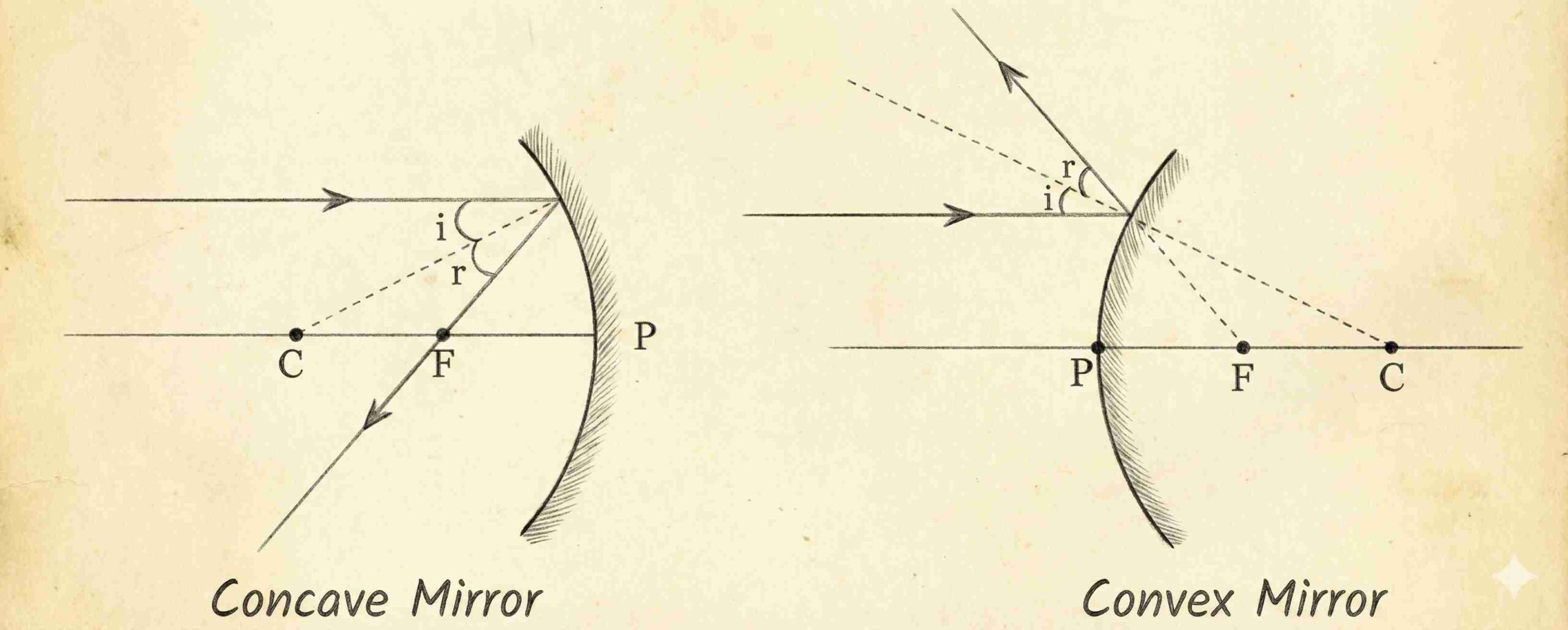
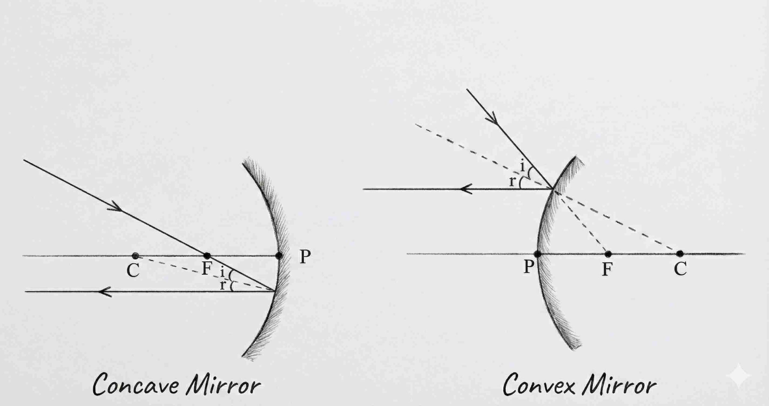
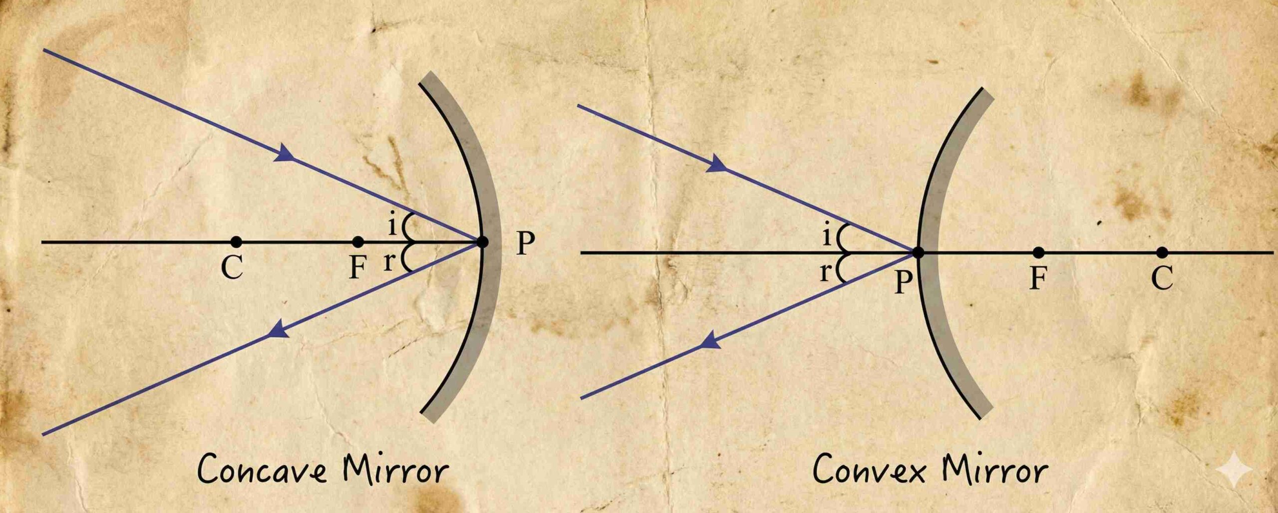
Ray incident at pole (P) →
- Reflects obliquely obeying laws of reflection (angle i = angle r with principal axis).
Also Read| Electricity Short Notes
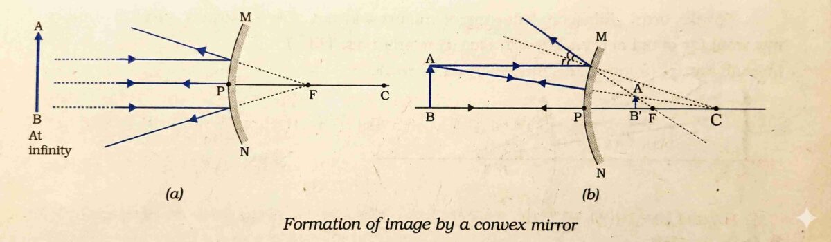
Convex Mirror – Image Characteristics
| Object Position | Image Position | Size | Nature |
|---|---|---|---|
| At infinity | At F (behind mirror) | Highly diminished, point-sized | Virtual, erect |
| Between infinity and P | Between P and F (behind) | Diminished | Virtual, erect |
Key Points:
- Image is always virtual, erect, and diminished, regardless of object position.
- Provides a wider field of view.
Uses of Convex and Concave Mirrors
Concave Mirror
- Torches, searchlights, vehicle headlights (to produce parallel beams).
- Shaving and dental mirrors (magnified image).
- Solar furnaces (concentrate sunlight at a focus).
Convex Mirror
- Rear-view (wing) mirrors in vehicles.
- Security/surveillance (e.g., full view of the Taj Mahal from the Agra Fort).
Preferred due to erect image, wide field of view, and diminished but safe representation of traffic.
Sign Convention for Reflection by Spherical Mirrors
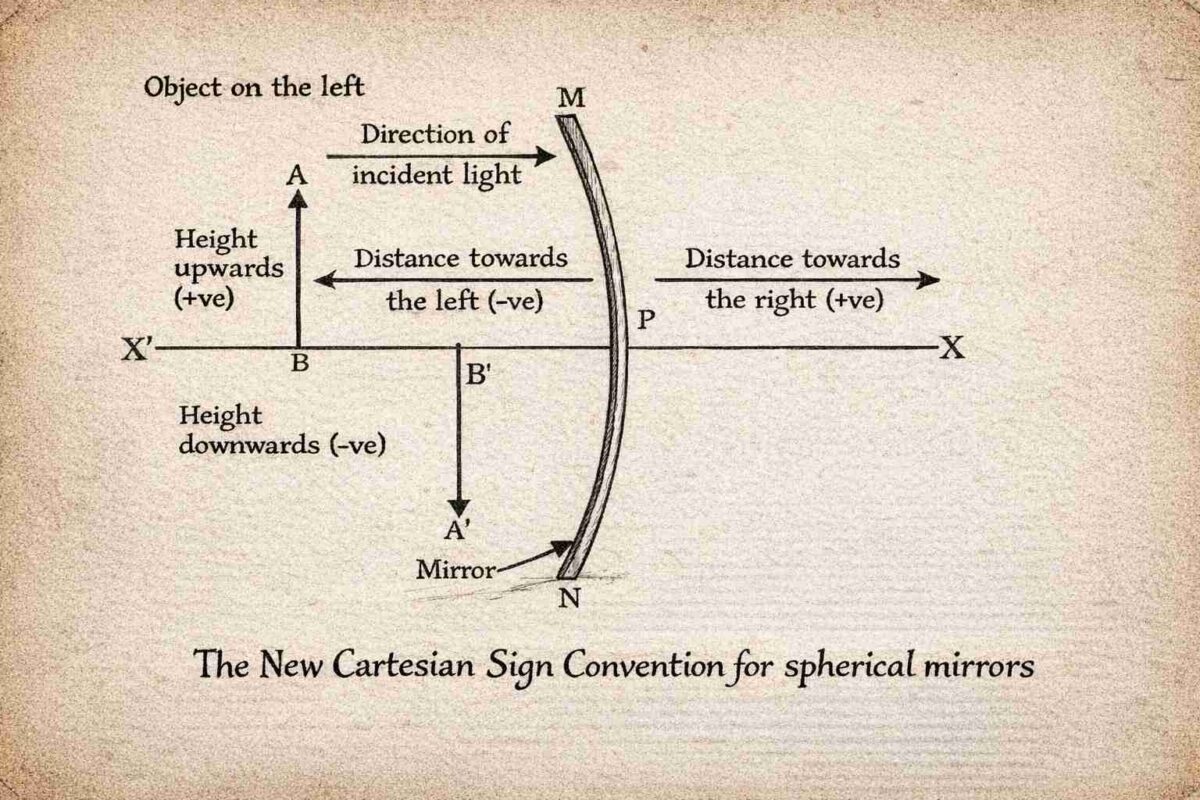
- Pole (P) is the origin; principal axis = x-axis.
- Object is always placed to the left of the mirror → light travels left to right.
- Distances measured from pole (P):
- Along principal axis (x-direction):
- Right of P (+x) → positive
- Left of P (–x) → negative
- Perpendicular to axis (y-direction):
- Above principal axis (+y) → positive
- Below principal axis (–y) → negative
- Along principal axis (x-direction):
Key implications:
- Object distance (u) is always negative (object is left of pole).
- Focal length (f):
- Concave mirror: f is negative (focus is in front, left of P).
- Convex mirror: f is positive (focus is behind, right of P).
- Image distance (v):
- Negative if image is in front (real image, concave mirror).
- Positive if image is behind mirror (virtual image).
Mirror Formula
- Valid for all spherical mirrors and all object positions.
- Always apply the sign convention when substituting values.
Magnification (m)
- Sign of m indicates the nature of the image:
- m > 0 (positive) → Virtual and erect image.
- m < 0 (negative) → Real and inverted image.
- Magnitude of m:
- |m| > 1 → Enlarged
- |m| = 1 → Same size
- |m| < 1 → Diminished
Note: Object height (h) is taken as positive (placed above the axis).
Image height (h’) is positive for virtual, negative for real images — consistent with the sign in
REFRACTION OF LIGHT
What is Refraction?
- Refraction is the bending of light when it travels obliquely from one transparent medium to another.
- Caused by a change in the speed of light in different media.
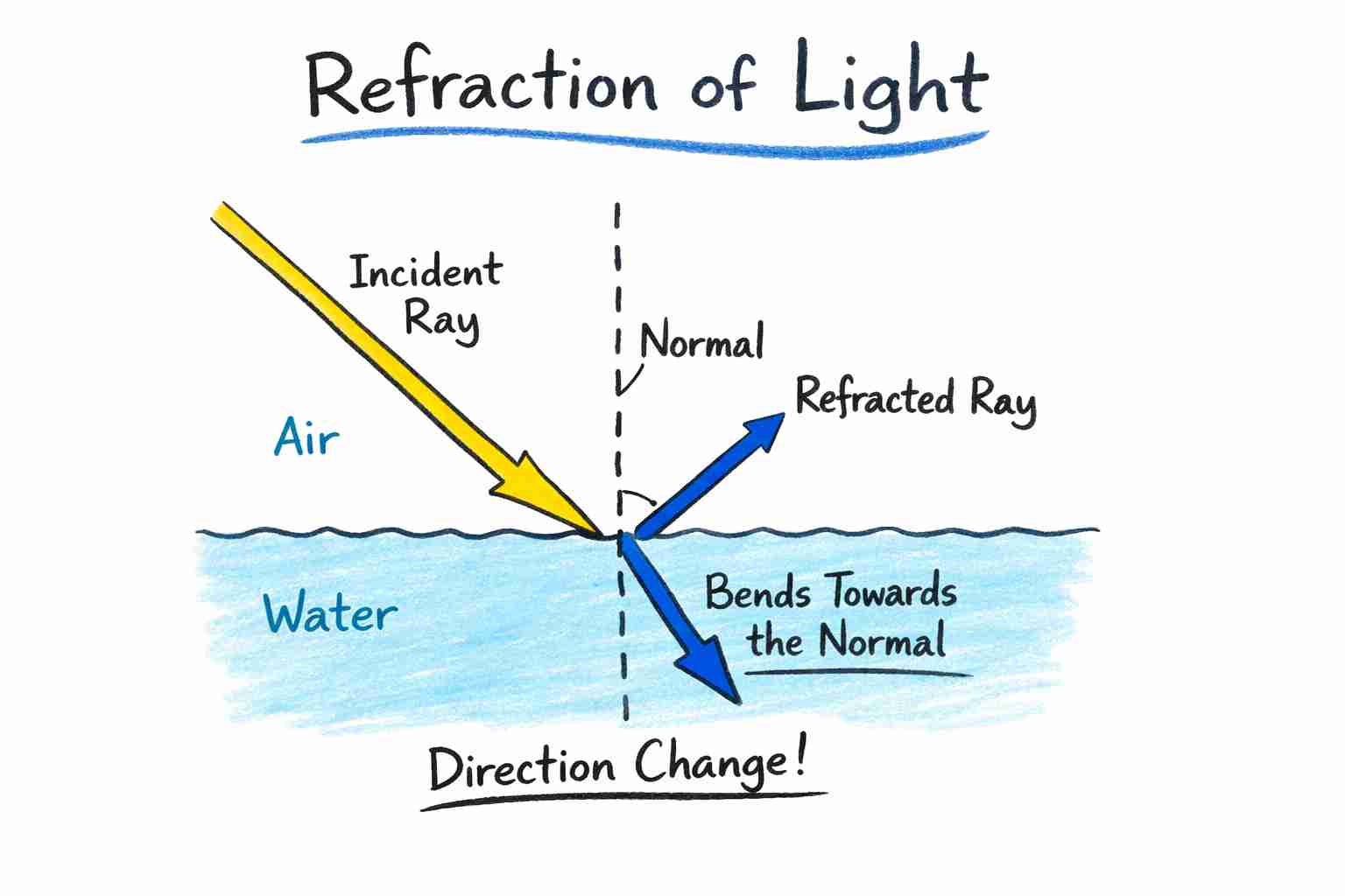
The extent of bending depends on the pair of media (e.g., water vs. kerosene, glass vs. plastic).
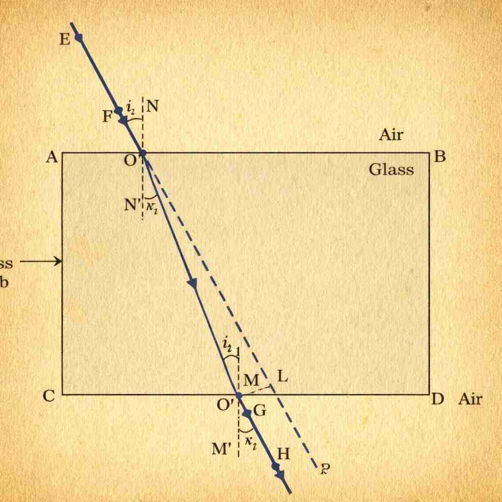
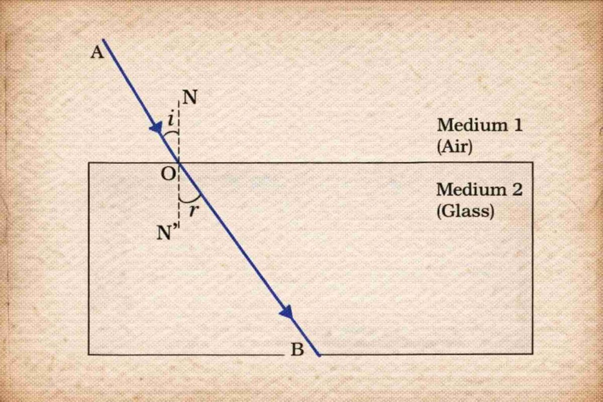
Refraction Through a Rectangular Glass Slab
- Light bends twice:
- Emergent ray is parallel to the incident ray (due to equal & opposite bending at parallel faces).
- But the emergent ray undergoes a lateral shift (sideways displacement).
- If light is incident normally (angle = 0°), no bending occurs; it goes straight.
Laws of Refraction (Snell’s Law)
1. The incident ray, refracted ray, and normal at the point of incidence all lie in the same plane.
2. Snell’s Law
Refractive Index
The refractive index measures how much light bends (refracts) when entering a material.
- The constant in Snell’s law defines how much a medium slows down light compared to another.
- Determines the degree of bending during refraction.
- where:
- = angle of incidence,
- = angle of refraction.
- This constant is the refractive index of the second medium w.r.t the first.
The Refractive Index
- Refractive index quantifies how much light bends when moving between two media.
- It is directly related to the change in the speed of light in different media.
Relative Refractive Index
- When light travels from
medium 1 to medium 2:
- Similarly, refractive index of medium 1 w.r.t. medium 2:
Absolute Refractive Index
When medium 1 is air or vacuum, the refractive index of medium 2 is called the absolute refractive index:
- c ≈ 3 × 10⁸ m/s (speed of light in vacuum/air).
- Examples:
- Water: → light travels 1.33 times slower in water than in air.
- Crown glass:
Note: You do not need to memorize exact values—understand their meaning.
Optical Density vs. Mass Density
- Optical density refers to refractive index, not mass per unit volume.
- A medium with a higher refractive index is optically denser, even if its mass density is lower.
→ Example: Kerosene is optically denser than water (nkerosene>nwater), but less dense by mass.
Key Implications
- Light slows down in optically denser media.
- Greater refractive index → greater bending toward the normal when entering from a rarer medium
Refraction by Spherical Lenses
What is a Lens?
A lens is a transparent optical device bounded by two surfaces, at least one of which is spherical.
Common types
Convex lens (converging lens)
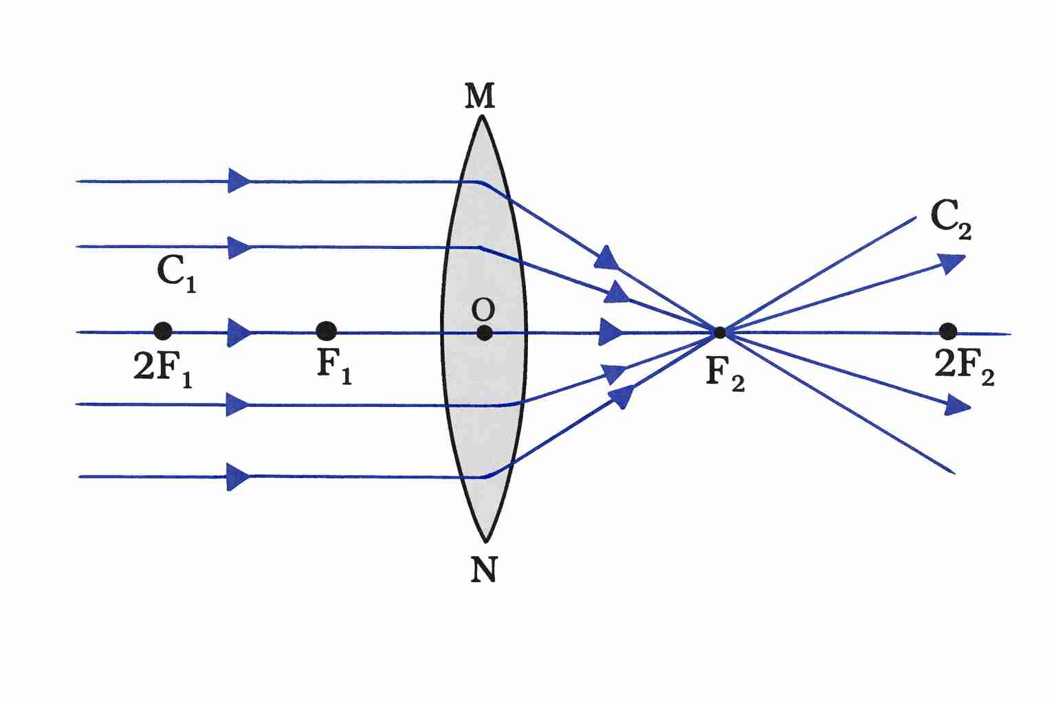
- Thicker at the centre, thinner at the edges.
- Converges parallel rays to a point.
Concave lens (diverging lens)
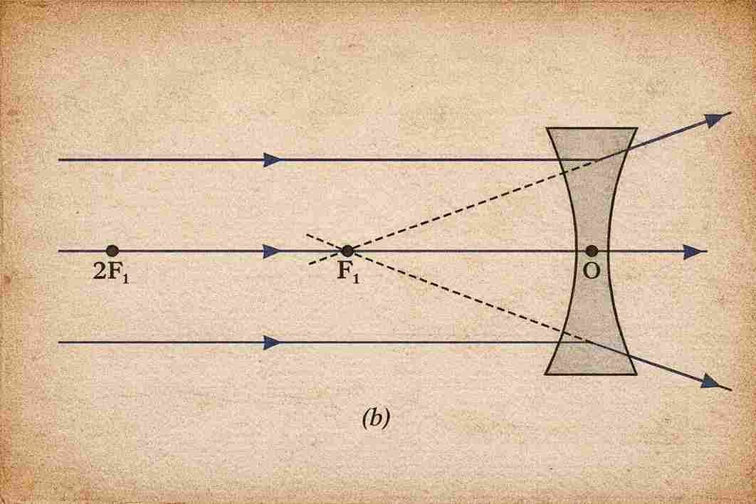
- Thinner at the centre, thicker at the edges.
- Diverges parallel rays as if from a point.
Key Terms
- Centres of curvature (C₁, C₂): Centres of the spheres of which the lens surfaces are parts.
- Principal axis: Imaginary line passing through C₁ and C₂.
- Optical centre (O): Central point of the lens.
→ A ray passing through O goes undeviated. - Aperture: Effective diameter of the lens’s circular outline.
→ We consider thin lenses with small apertures (aperture ≪ radius of curvature).
Principal Focus & Focal Length
Convex lens: Parallel rays converge at a real focus (F) on the opposite side → real principal focus.
Concave lens: Parallel rays diverge after refraction; appear to come from a point on the same side → virtual principal focus.
Each lens has two principal foci: F₁ and F₂, one on each side.
Focal length (f): Distance between optical centre (O) and principal focus (F).
Practical method to find the focal length of a convex lens:
Focus sunlight using the lens on paper—the distance from the lens to the bright spot (image of the Sun) ≈ focal length.
Nature of Lenses
| Thin in the middle, thick at the edges | Shape | Effect on Parallel Rays | Focus Type |
|---|---|---|---|
| Convex | Thick in middle | Converges | Real (F) |
| Concave | Thin in middle, thick at edges | Diverges | Virtual (F) |
Note: Both lenses obey the laws of refraction at each surface.
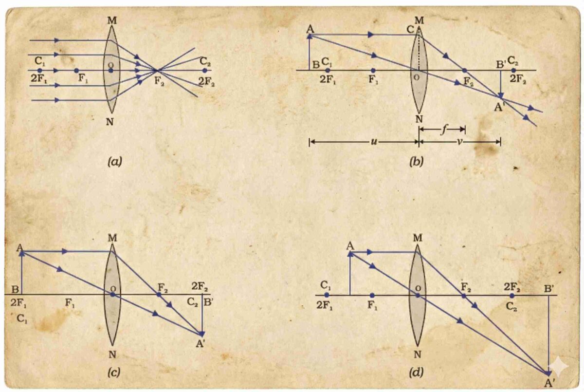
Image Formation by Lenses
Convex Lens (Converging Lens)
Image characteristics depend on object position:
| Object Position | Image Position | Size | Nature |
|---|---|---|---|
| At infinity | At F₂ | Highly diminished, point-sized | Real, inverted |
| Beyond 2F₁ | Between F₂ and 2F₂ | Diminished | Real, inverted |
| At 2F₁ | At 2F₂ | Same size | Real, inverted |
| Between F₁ and 2F₁ | Beyond 2F₂ | Enlarged | Real, inverted |
| At F₁ | At infinity | Highly enlarged | Real, inverted |
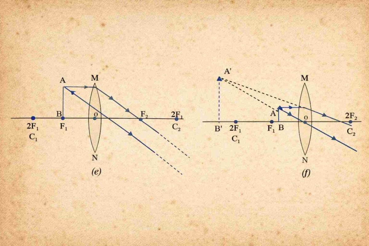
| Between F₁ and O | Same side as object | Enlarged | Virtual, erect |
Note: Only when the object is between F₁ and optical centre (O) is the image virtual and erect; all other cases give real and inverted images.
Concave Lens (Diverging Lens)
Always produces the same type of image, regardless of object position:
| Object Position | Image Position | Size | Nature |
|---|---|---|---|
| At infinity | At F₁ (on same side) | Highly diminished, point-sized | Virtual, erect |
| Between infinity and O | Between F₁ and O | Diminished | Virtual, erect |

Conclusion:
- Concave lens always forms a virtual, erect, and diminished image.
- Image is located between F₁ and O, on the same side as the object.
Key Comparison
- Convex lens: Can produce real or virtual images; size varies (diminished, same, or enlarged).
- Concave lens: Only virtual, erect, and diminished images—no real image possible.
Image Formation in Lenses Using Ray Diagrams
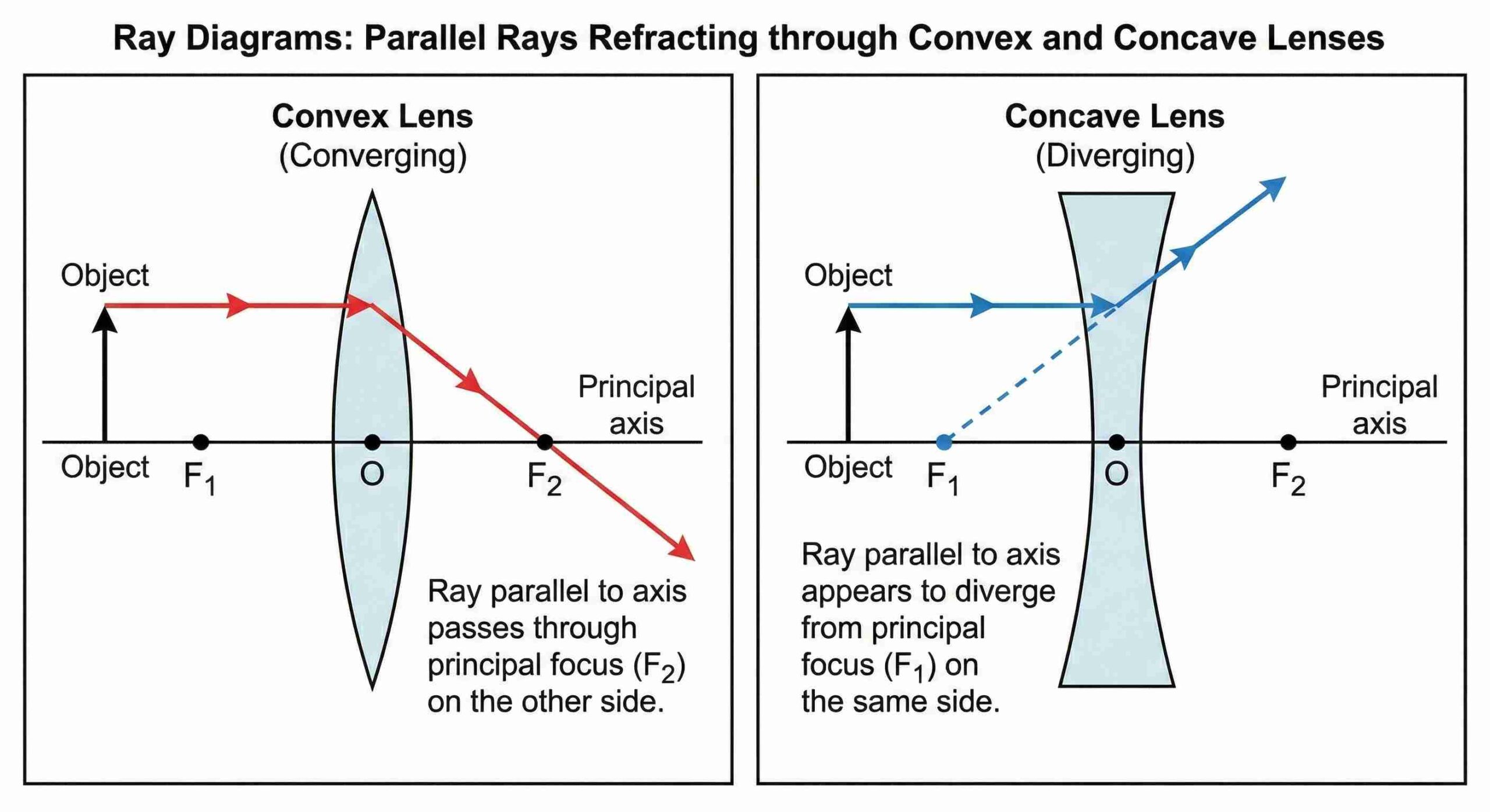
Ray is parallel to principal axis
- Convex lens: After refraction, passes through F₂ (focus on opposite side).
- Concave lens: After refraction, it appears to diverge from F₁ (focus on the same side).
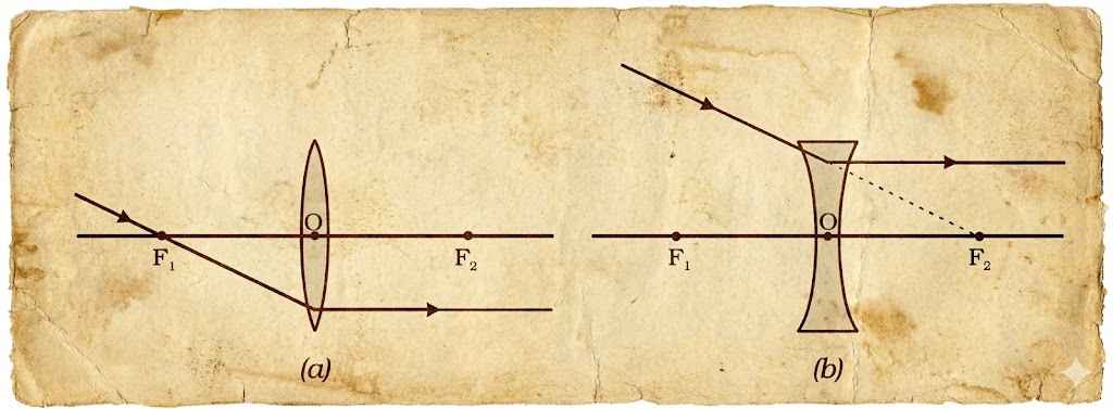
Ray through a focus
- Convex lens: A ray passing through F₁ emerges parallel to the principal axis after refraction.
- Concave lens: A ray heading toward F₂ (on the opposite side) refracts and emerges parallel to the principal axis.
Ray through optical centre (O)
- Passes undeviated through the lens in both convex and concave cases.
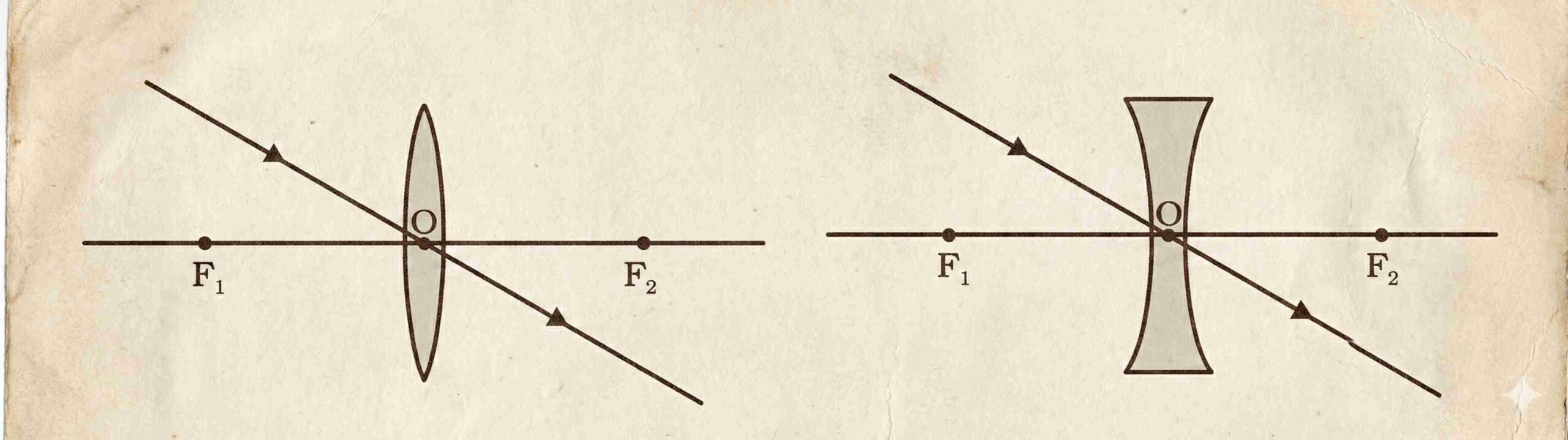
The point of intersection of any two refracted rays gives the position of the image.
If refracted rays diverge, extend them backward (dashed lines); their intersection gives the virtual image location.
Lens Formula, Magnification & Power of a Lens
Lens Formula
- v = image distance
- u = object distance
- f = focal length
✅ Applies to all spherical lenses (convex and concave) in all situations.
⚠️ Always use the New Cartesian Sign Convention when substituting values.
Sign Convention (Recap for Lenses)
- Object is placed to the left → u is negative.
- Convex lens: f is positive (converging).
- Concave lens: f is negative (diverging).
- v is positive for real images (on the opposite side of the object).
- v is negative for virtual images (on the same side as the object).
Magnification (m)
- Positive m → Virtual and erect image.
- Negative m → Real and inverted image.
- |m| > 1 → Enlarged
- |m| = 1 → Same size
- |m| < 1 → Diminished
Note: Unlike mirrors, no negative sign in m=v/u for lenses—sign of v and u already accounts for orientation.
Power of a Lens (P)
- f must be in metres (m).
- SI unit: Dioptre (D) →
Sign of Power:
- Convex lens: f > 0 → P > 0 (positive power, converging).
- Concave lens: f < 0 → P < 0 (negative power, diverging).
Examples:
- Lens of +2.0 D → Convex,
- Lens of –2.5 D → Concave,
Used by opticians in prescribing corrective eyeglasses.
Conclusion: Light Reflection and Refraction Short Notes
In this chapter, we learned how light behaves when it reflects from mirrors and refracts through lenses. These ideas help us understand how images are formed and how many useful devices like spectacles, cameras, microscopes, and telescopes work.
To master this chapter, students should learn the laws clearly, practice ray diagrams regularly, and solve numerical problems daily. With regular practice, Light – Reflection and Refraction becomes easy, logical, and scoring.