
“Magnetic Effects of Electric Current Short Notes” is a quick, exam-focused summary of Class 10 Chapter 12. They cover magnetic fields, solenoids, Fleming’s rules, and domestic circuits in simple language and short points.
Only important concepts are included, with keywords highlighted for fast revision and easy recall. Confusing ideas and extra details are removed to keep learning clear and focused.
“Use these notes for quick revision, not for first learning.
Read NCERT first → revise with these notes → remember better.“
Introduction
1. Core Concept
- Electricity and magnetism are fundamentally linked
- Electric current produces a magnetic effect
2. Key Observations
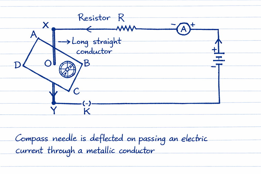
- Current-carrying wire acts like a magnet
- The magnetic needle deflects near a current-carrying conductor
- Demonstrates a magnetic field around a conductor
3. Reverse Phenomenon
- Moving magnets can produce an electric effect
- Basis of electromagnetic induction
Magnetic Field And Magnetic Field Lines
1. Magnet Basics
- Compass needle = small bar magnet
- North pole: end pointing north (north-seeking)
- South pole: end pointing south (south-seeking)
- Like poles repel; unlike poles attract
2. Magnetic Field
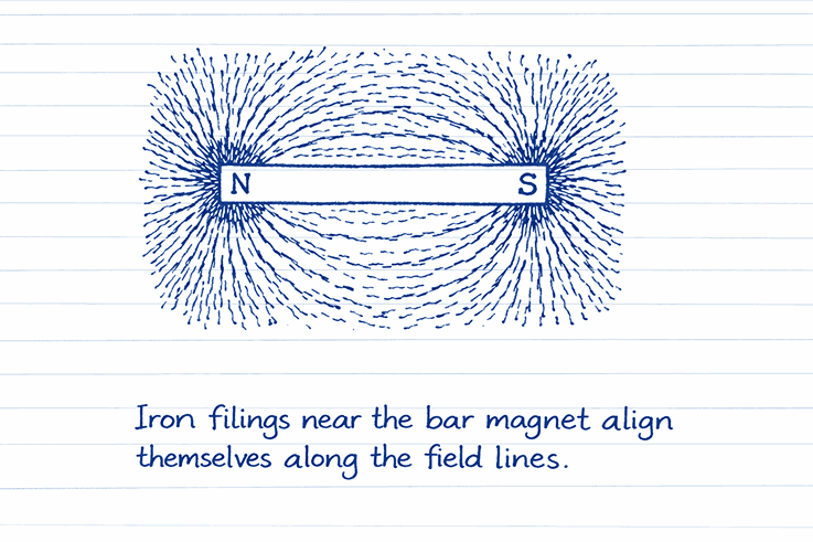
- The region around a magnet where its force is detectable
- Demonstrated by a pattern of iron filings
- Has both direction and magnitude
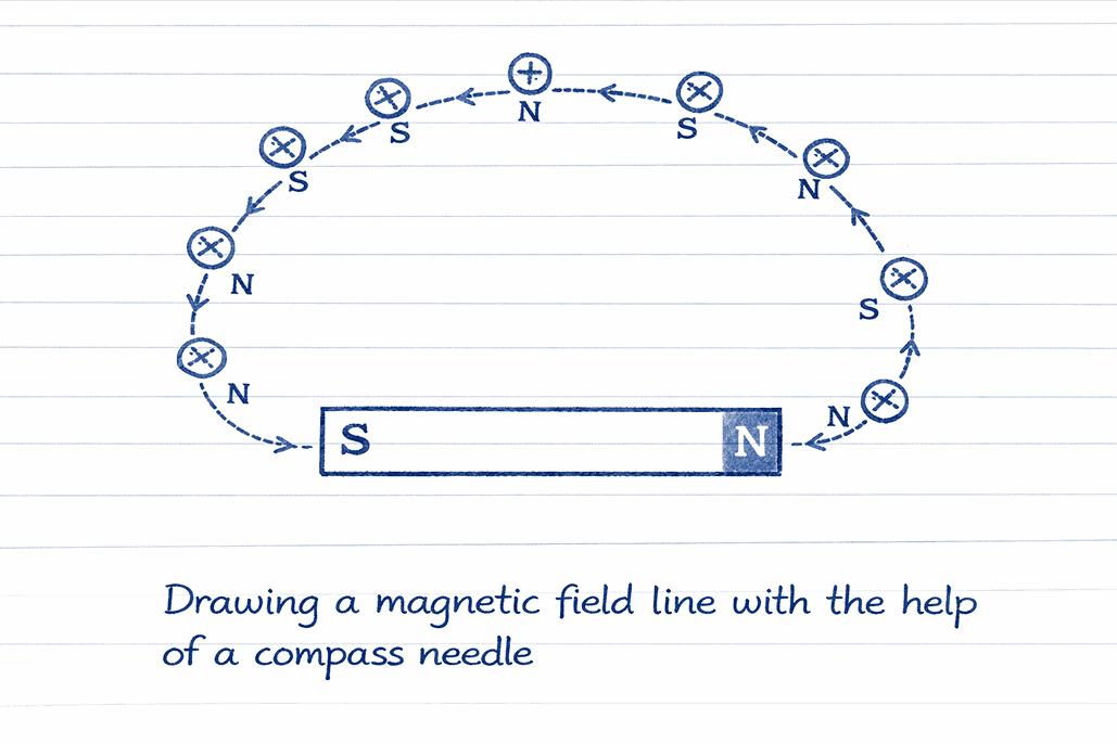
3. Magnetic Field Lines
- Definition: Imaginary lines along which iron filings align
- Show direction and strength of the magnetic field
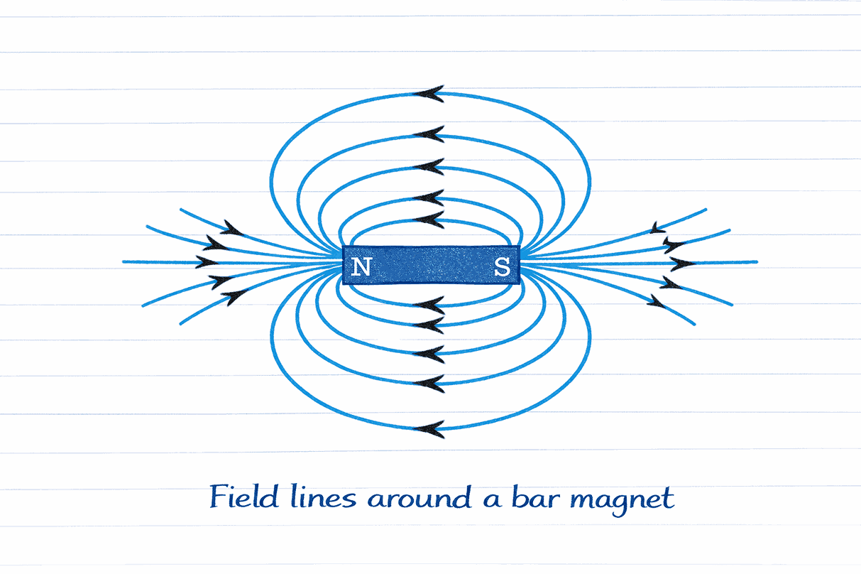
4. Properties of Field Lines
- Emerge from the North Pole → enter the South Pole (outside magnet)
- Inside magnet: run South → North pole
- Form closed curves (continuous loops)
- Closer lines = stronger field
- Never intersect (a compass can’t point two directions at once)
Direction Convention
- Field direction = direction the north pole of the compass needle moves
- Arrows marked: N → S externally
Magnetic Field: Current-Carrying Conductor

1. Basic Principle
- Electric current in a conductor → produces a magnetic field around it
- The field pattern depends on the shape of the conductor
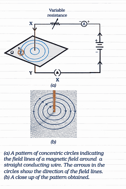
2. Straight Conductor
- Field lines form concentric circles around the wire
- Circles become larger with increasing distance from the wire
3. Factors Affecting Field Strength
Current (I)
- More current → stronger magnetic field
- Stronger field → compass needle deflects more
👉 So, field strength increases with current
Distance (r)
- Larger distance from the wire → weaker magnetic field
- Weaker field → compass needle deflects less
👉 So, field strength decreases as distance increases
In short (simple rule)
✅ Field strength ∝ Current
✅ Field strength ∝ 1 / Distance
Meaning:
- Double the current → field becomes double
- Double the distance → field becomes half
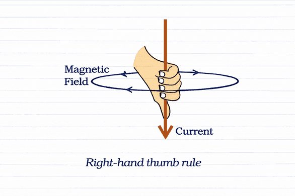
4. Right-Hand Thumb Rule
- Hold the conductor in your right hand
- Thumb → points in the current direction
- Curl fingers → show magnetic field direction (clockwise/anticlockwise)
Magnetic Field due to a Current through a
Circular Loop
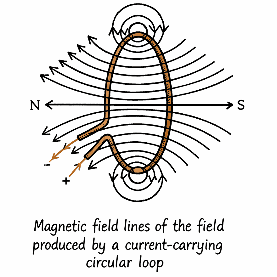
1. Field Pattern
- Straight wire bent into circular loop → field lines form concentric circles around wire
- At the center of the loop, arcs appear as straight lines
- All wire sections contribute a field in the same direction inside the loop → fields add up
2. Current (I)
- More current → stronger magnetic field
- Less current → weaker magnetic field
Relation:
Field strength ∝ Current
👉 If current doubles, the magnetic field also doubles.
3. Number of turns (n)
- Each loop of wire produces its own magnetic field
- All loops have the same current direction, so their fields add together
So,
Field of coil = n × field of one turn
Relation:
Field strength ∝ Number of turns
👉 If it turns double, the magnetic field doubles.
Magnetic field strength depends on both:
Where:
- = number of turns
- = current
Magnetic Field due to a Current in a Solenoid
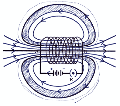
1. What is Solenoid
- Cylindrical coil of many closely wound insulated copper wire turns
- Acts as a strong electromagnet when current flows
2. Magnetic Field Pattern
- Field lines are identical to bar magnet
- One end → North pole; opposite end → South pole
- Inside the solenoid: field lines are parallel straight lines
- Indicates uniform magnetic field (same strength & direction at all interior points)
3. Field Strength Factors
- ∝ Current: ↑ current → ↑ field strength
- (Increasing current increases field strength)
- ∝ Number of turns: more turns → stronger field
- (More turns of wire lead to a stronger field)
- Core material: inserting a soft iron core greatly amplifies field
4. Electromagnet
- Formed by placing soft iron inside a current-carrying solenoid
- Becomes strong temporary magnet
- Magnetism disappears when the current stops
FORCE ON A CURRENT-CARRYING CONDUCTOR IN A MAGNETIC FIELD
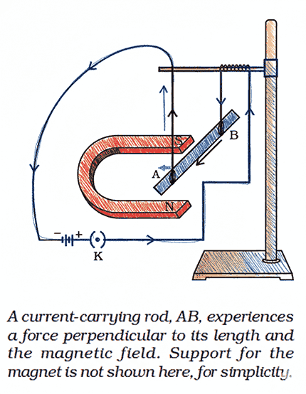
1. Basic Principle
- A current-carrying conductor in a magnetic field experiences a force
- Ampere’s law: A magnet exerts an equal & opposite force on a conductor
2. Force Direction
- Depends on:
- Direction of current
- Direction of magnetic field
- Reversing current → reverses force direction
- Reversing field → reverses force direction
- Force is always perpendicular to both current and field
3. Force Magnitude
- Maximum when the current ⊥ magnetic field (90° angle)
- Zero when the current ∥ magnetic field
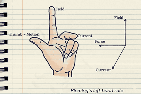
3. Fleming’s Left-Hand Rule
- Thumb → Force / Motion direction
- Forefinger → Magnetic field direction (N → S)
- Middle finger → Current direction (+ve → -ve)
- All three fingers are mutually perpendicular
Applications
- Electric motor
- Loudspeakers
- Microphones
- Measuring instruments (ammeters, galvanometers)
DOMESTIC ELECTRIC CIRCUITS
1. Power Supply
- Mains supply: 220 V via overhead poles or underground cables
- Live wire: Red insulation (carries current)
- Neutral wire: Black insulation (return path)
- Earth wire: Green insulation (safety)
2. House Wiring Layout
- Wires enter via meter board → electricity meter → main fuse → main switch
- Two separate circuits:
- 15 A circuit: High-power appliances (geysers, ACs, coolers)
- 5 A circuit: Low-power devices (bulbs, fans)
3. Earthing (Safety)
- Earth wire connected to metal plate buried deep in the ground
- Metallic appliance bodies linked to the earth wire
- Provides a low-resistance path for leakage current
- Prevents electric shock by keeping appliance potential = earth’s potential
4. Circuit Design
- Appliances connected in parallel
- Ensures equal potential difference (220 V) across all devices
- Each appliance has an independent switch for ON/OFF control
5. Electric Fuse
- Purpose: Prevents damage from overloading and short-circuiting
- Working: High current → Joule heating → fuse melts → circuit breaks
- Placed in live wire before appliance connection
6. Faults
- Short-circuiting:
- Live & neutral wires touch directly
- Caused by damaged insulation or appliance fault
- Results in sudden high current
- Overloading:
- Too many appliances on one socket
- Voltage surge in supply
- Exceeds circuit current rating
Conclusion: Magnetic Effects of Electric Current Short Notes
Mastery comes through repetition—not a single read. These short notes distill Chapter 12 into high-yield, exam-ready points, but true confidence builds when you revise again and again.
Return to these notes daily: visualize field lines, practice Fleming’s left-hand rule with your fingers, and rehearse safety concepts until they become instinctive.
Each revision sharpens recall, eliminates confusion, and transforms theory into exam-ready knowledge. Don’t just read once—revise repeatedly. Your board’s success depends on it.
Also Read | Short Notes – Light Reflection and Refraction Short Notes Class 10